


Industry
 Num:67
 See:2530
2021-05
08
Detail these two kinds of common overcurrent protection!
Overcurrent protection is a standard for power supply. It can be said that all power supplies will have overcurrent protection function. Overcurrent protection can be divided into two kinds: turn-off protection and current limiting protection.
Shut-off protection means that when overloaded, the circuit detects that the power supply is overcurrent, and the power chip stops PWM, and the overcurrent fault is removed, it will not return to normal.
The current limiting type is widely used because of its current droop characteristics, and the switching power supply can automatically resume work after the fault is lifted. At present, many chips have two detection points. The first detection point detects the current overcurrent and turns off the current PWM. When the overcurrent recovers, the PWM will return to normal.
For current limiting power supply detection, most of the time we are in series with a power resistor under MOSFET, and then use RC filter to give the chip overcurrent detection point. R2 in Figure 1 is the current limiting resistor, and R5 and C4 constitute the RC filter.

R2 resistance in the selection of a few things to pay attention to:
1. Resistance value of current limiting resistor R2
2. Power selection of current limiting resistor
3. Material of current limiting resistor
Choose the value of resistor, according to the side of the peak current Ipk and CS feet detect over-current voltage, that the maximum voltage from CS on general resistance voltage over-current protection point of 70%, then according to the calculated value set by the voltage and current, we know the value after the original edge RMS current can be calculated based on the actual power of each cycle, The power required by the resistor is selected according to the actual power consumption, and the power selected is 3-4 times of the actual power.
After selecting the resistance value and power of the current limiting resistor, it is necessary to select the material. The current limiting resistor can be used with plug-ins or patches. When using plug-ins, it is necessary to pay attention to not using inductive resistors, which is a special need to pay attention to.
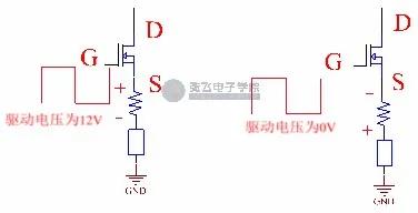
This resistor is selected with an accuracy of 1% and is non-inductive. If the inductive resistor is used, what will happen? Let's analyze it:
First of all, when the drive is at a high level, it is assumed that G has a voltage of 12V to the ground. When the MOS tube is turned on, because the DI /dt is relatively large, the inductance of the inductive resistor may have positive and negative voltages up and down. At this time, the voltage of GS point is less than 12V.
When the driver for the low level, G to ground is 0 v voltage, MOS tube shut off, at this time the stray inductance appeared on negative under positive voltage, because the MOS tube shut off, no current flows through, the current limiting resistor voltage is 0 v, S pole is the emergence of a negative pressure, and G is 0 v, the voltage between the GS and parasitic inductance on the voltage amplitude, If the parasitic inductance is large, there may be a second opening. So when you choose a resistor, you need to choose an inductive resistor.
The current limiting resistor connects a RC to the chip, and the RC function is used for filtering. Nowadays, many chips have a front blanking function, but the front blanking time may not be enough, so the RC is still added. As we can see in the following diagram, the voltage waveform on the current limiting resistor has a big oscillation. Sometimes the spike of the oscillation will exceed our current limiting voltage, but this is caused by parasitic parameters, which is generally difficult to control. After RC filtering, the waveform at point B will no longer have this oscillation, it will be filtered out by RC. RC is designed according to the cut-off frequency, which is generally 10-30 times of the switching frequency. If the switching frequency is 60kHz, we will choose 1K resistor and 100pF capacitor, and the roughly cut-off frequency is 1591kHz.
Edge blanking is the function of the chip
This function is that after the chip sends out the drive waveform and the MOS tube is turned on, it will not detect whether the current is overcurrent for a period of time, which is about 200-300ns. Different chips are different. Along with the increase of power, the original edge of MOS tube current also get bigger, so our current limiting resistance loss will increase, when reaches a certain value, need to select a very small resistor resistance, may be the small resistance to walk line parasitic resistance on the PCB will be on the resistance of a certain proportion, the resistance is not good for selection. This time no longer choose current limiting resistors, and use the transformer to do current limiting, transformer itself is a magnetic device, usually is the proportion of 1:100, it is a inductance, we analyzed in front of the MOS tube series resistance, resistance can't use inductive, transformer itself is now a inductance, so we need to change the connection, As shown in the figure below:
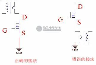
When the transformer is applied, it should be noted that it cannot be connected to the S pole of the MOS tube, but it is usually connected to the D pole, for the same reason as the inductive resistor.
Shut-off protection means that when overloaded, the circuit detects that the power supply is overcurrent, and the power chip stops PWM, and the overcurrent fault is removed, it will not return to normal.
The current limiting type is widely used because of its current droop characteristics, and the switching power supply can automatically resume work after the fault is lifted. At present, many chips have two detection points. The first detection point detects the current overcurrent and turns off the current PWM. When the overcurrent recovers, the PWM will return to normal.
For current limiting power supply detection, most of the time we are in series with a power resistor under MOSFET, and then use RC filter to give the chip overcurrent detection point. R2 in Figure 1 is the current limiting resistor, and R5 and C4 constitute the RC filter.
R2 resistance in the selection of a few things to pay attention to:
1. Resistance value of current limiting resistor R2
2. Power selection of current limiting resistor
3. Material of current limiting resistor
Choose the value of resistor, according to the side of the peak current Ipk and CS feet detect over-current voltage, that the maximum voltage from CS on general resistance voltage over-current protection point of 70%, then according to the calculated value set by the voltage and current, we know the value after the original edge RMS current can be calculated based on the actual power of each cycle, The power required by the resistor is selected according to the actual power consumption, and the power selected is 3-4 times of the actual power.
After selecting the resistance value and power of the current limiting resistor, it is necessary to select the material. The current limiting resistor can be used with plug-ins or patches. When using plug-ins, it is necessary to pay attention to not using inductive resistors, which is a special need to pay attention to.
This resistor is selected with an accuracy of 1% and is non-inductive. If the inductive resistor is used, what will happen? Let's analyze it:
First of all, when the drive is at a high level, it is assumed that G has a voltage of 12V to the ground. When the MOS tube is turned on, because the DI /dt is relatively large, the inductance of the inductive resistor may have positive and negative voltages up and down. At this time, the voltage of GS point is less than 12V.
When the driver for the low level, G to ground is 0 v voltage, MOS tube shut off, at this time the stray inductance appeared on negative under positive voltage, because the MOS tube shut off, no current flows through, the current limiting resistor voltage is 0 v, S pole is the emergence of a negative pressure, and G is 0 v, the voltage between the GS and parasitic inductance on the voltage amplitude, If the parasitic inductance is large, there may be a second opening. So when you choose a resistor, you need to choose an inductive resistor.
The current limiting resistor connects a RC to the chip, and the RC function is used for filtering. Nowadays, many chips have a front blanking function, but the front blanking time may not be enough, so the RC is still added. As we can see in the following diagram, the voltage waveform on the current limiting resistor has a big oscillation. Sometimes the spike of the oscillation will exceed our current limiting voltage, but this is caused by parasitic parameters, which is generally difficult to control. After RC filtering, the waveform at point B will no longer have this oscillation, it will be filtered out by RC. RC is designed according to the cut-off frequency, which is generally 10-30 times of the switching frequency. If the switching frequency is 60kHz, we will choose 1K resistor and 100pF capacitor, and the roughly cut-off frequency is 1591kHz.
Edge blanking is the function of the chip
This function is that after the chip sends out the drive waveform and the MOS tube is turned on, it will not detect whether the current is overcurrent for a period of time, which is about 200-300ns. Different chips are different.
When the transformer is applied, it should be noted that it cannot be connected to the S pole of the MOS tube, but it is usually connected to the D pole, for the same reason as the inductive resistor.
Share


- About
- Company Profile
- Company Honor
- Products
- FIELD EFFECT TRANSISTOR
- SCHOTTKY DIODES
- ULTRAFAST RECOVERY POWER RECTIFIER
- SIC SCHOTTKY DIODES
- Silicon carbide MOSFET
- Follow
-
Address:Room 402-404,Qianhai ChengJin Building,Moon Bay Boulevard, Nanshan District,Shenzhen
Tel:0755-88327180
Fax:0755-88327190
Email:sunny@hisemicon.com
- Contact
-
.jpg)
WeChat