


Industry
 Num:69
 See:1449
2021-05
25
Common four types of constant current source circuit analysis and application, too practical!
As shown in Figure 1, the mirror constant current source circuit consists of two tubes VT0 and VT1 with exactly the same characteristics. Because the C and B poles of the VT0 tube are connected, UCE0=UBE0, that is, VT0 is in the amplifying state, and collector current IC0=β0*IB0. In addition, the B-E of tubes VT0 and VT1 are connected separately, so their base current IB0=IB1= Ib. If the current amplification factor β0=β1=β, then the collector current IC0=IC1=IC=β* Ib. It can be seen that because of this special connection method of the circuit, the two collector IC1 and IC0 are mirrored, so this circuit is called a mirrored constant current source (Ir is the reference current, and IC1 is the output current).
Mirror constant current source circuit
The constant current source can not only provide the appropriate static current for the amplifier circuit, but also can be used as an active load to replace the high resistance value of the resistance, so as to increase the voltage amplification of the amplifier circuit. This usage has a very wide range of applications in integrated op-amp circuits. This section will introduce the common constant-current source circuit and its application as an active load, so as to reserve knowledge for the following contents.
In the modified differential amplifier, constant current source to replace emitter resistor RE, set up a suitable both for differential amplifier circuit static working current, and greatly enhance the common-mode feedback effect, make the circuit has the stronger ability to suppress common mode signal, and does not need high power voltage, so the constant current source and differential amplifier circuit is a perfect fit!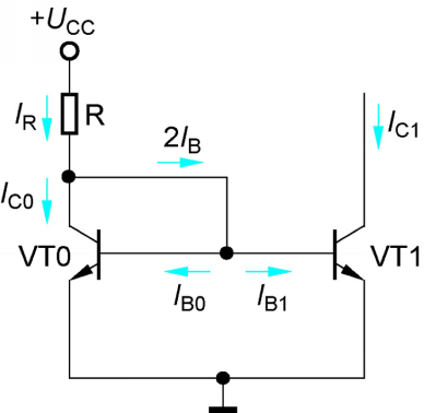
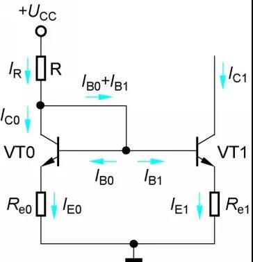
When RE0 = RE1, IC1 is still equal to IR, but the IR of this circuit is specified by Equation (2-4), which is smaller than that of Equation (2-2), and is generally used in the input stage of the preamplifier.
Like a typical static point stabilization circuit, RE0 and RE1 are current negative feedback resistors, so the output current IC1 of a proportional constant current source has higher stability than that of a mirror constant current source circuit.
As shown in Fig. 2, the proportional constant current source circuit consists of two tubes VT0 and VT1 with identical characteristics. The emitters of the two tubes are respectively serially connected with resistors RE0 and RE1. The proportional constant current circuit source changes the relation between IC1≈ Ir, so that IC1 is proportional to Ir, thus overcoming the disadvantage of the mirror constant current circuit source.
Proportional constant current source circuit
The mirror constant current source circuit is simple and widely used. However, when the supply voltage is constant, if IC1 is large, then IR is bound to increase, and the power consumption of resistor R will increase, which should be avoided in integrated circuits. If IC1 is required to be small, then IR is bound to be small, and the value of resistance R will be large, which is difficult to achieve in integrated circuits. Therefore, people think of using other methods to solve the problem, so that other current source circuits can be derived.

Multiple constant current source circuit
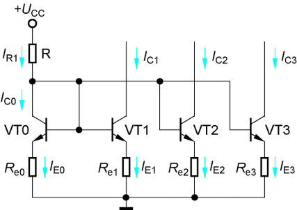
Integrated op amp is a multistage amplifier circuit, so it needs multiple constant current source circuits to provide appropriate static current for each level. A reference current can be used to obtain multiple different output currents to suit the needs of all levels.
The circuit shown in Figure 4 is a multi-channel constant-current source circuit based on a proportional constant-current source, with IR as the reference current and IC1, IC2 and IC3 as the three-channel output current. Since the values of voltage UBE between B-E of each tube are roughly equal, an approximate relationship can be obtained
IE0Re0 material IE1Re1 material IE2Re2 material IE3Re3 (2-6)
When IE0 is determined, the required current can be obtained at each level as long as the appropriate resistor is selected.
Mirror constant current source circuit
The constant current source can not only provide the appropriate static current for the amplifier circuit, but also can be used as an active load to replace the high resistance value of the resistance, so as to increase the voltage amplification of the amplifier circuit. This usage has a very wide range of applications in integrated op-amp circuits. This section will introduce the common constant-current source circuit and its application as an active load, so as to reserve knowledge for the following contents.
In the modified differential amplifier, constant current source to replace emitter resistor RE, set up a suitable both for differential amplifier circuit static working current, and greatly enhance the common-mode feedback effect, make the circuit has the stronger ability to suppress common mode signal, and does not need high power voltage, so the constant current source and differential amplifier circuit is a perfect fit!
When RE0 = RE1, IC1 is still equal to IR, but the IR of this circuit is specified by Equation (2-4), which is smaller than that of Equation (2-2), and is generally used in the input stage of the preamplifier.
Like a typical static point stabilization circuit, RE0 and RE1 are current negative feedback resistors, so the output current IC1 of a proportional constant current source has higher stability than that of a mirror constant current source circuit.
As shown in Fig. 2, the proportional constant current source circuit consists of two tubes VT0 and VT1 with identical characteristics. The emitters of the two tubes are respectively serially connected with resistors RE0 and RE1. The proportional constant current circuit source changes the relation between IC1≈ Ir, so that IC1 is proportional to Ir, thus overcoming the disadvantage of the mirror constant current circuit source.
Proportional constant current source circuit
The mirror constant current source circuit is simple and widely used. However, when the supply voltage is constant, if IC1 is large, then IR is bound to increase, and the power consumption of resistor R will increase, which should be avoided in integrated circuits. If IC1 is required to be small, then IR is bound to be small, and the value of resistance R will be large, which is difficult to achieve in integrated circuits. Therefore, people think of using other methods to solve the problem, so that other current source circuits can be derived.
Micro variable constant current source circuit
According to Equation (2-3), if RE0 is very small or even zero, then RE1 can obtain a small output current with only a small resistance. This circuit is called a micro-variable constant current source, as shown in Fig. 3. The static current of the input stage of the integrated op amp is very small, usually only dozens of microamps, or even smaller, so the micro-variable current source is mainly used in the active load of the input stage of the integrated op amp.
According to Equation (2-3), if RE0 is very small or even zero, then RE1 can obtain a small output current with only a small resistance. This circuit is called a micro-variable constant current source, as shown in Fig. 3. The static current of the input stage of the integrated op amp is very small, usually only dozens of microamps, or even smaller, so the micro-variable current source is mainly used in the active load of the input stage of the integrated op amp.
Multiple constant current source circuit
Integrated op amp is a multistage amplifier circuit, so it needs multiple constant current source circuits to provide appropriate static current for each level. A reference current can be used to obtain multiple different output currents to suit the needs of all levels.
The circuit shown in Figure 4 is a multi-channel constant-current source circuit based on a proportional constant-current source, with IR as the reference current and IC1, IC2 and IC3 as the three-channel output current. Since the values of voltage UBE between B-E of each tube are roughly equal, an approximate relationship can be obtained
IE0Re0 material IE1Re1 material IE2Re2 material IE3Re3 (2-6)
When IE0 is determined, the required current can be obtained at each level as long as the appropriate resistor is selected.
Share


- About
- Company Profile
- Company Honor
- Products
- FIELD EFFECT TRANSISTOR
- SCHOTTKY DIODES
- ULTRAFAST RECOVERY POWER RECTIFIER
- SIC SCHOTTKY DIODES
- Silicon carbide MOSFET
- Follow
-
Address:Room 402-404,Qianhai ChengJin Building,Moon Bay Boulevard, Nanshan District,Shenzhen
Tel:0755-88327180
Fax:0755-88327190
Email:sunny@hisemicon.com
- Contact
-
.jpg)
WeChat