


Industry
 Num:77
 See:2075
2021-07
21
Inductive current, that's all you care about!
Introduction to the
In the design of switching power supply, the design of inductance brings many challenges for engineers. The engineer should not only select the inductance value, but also consider the current the inductor can withstand, the winding resistance, the mechanical dimensions, and so on. This article focuses on the explanation: DC current effects on inductors. This will also provide the necessary information for selecting the appropriate inductor.
Understand the function of inductors
Inductance is often understood as the L in the LC filter circuit at the output of a switching supply (where C is the output capacitor). While this is true, understanding inductor design requires a deeper understanding of inductor behavior.
In a step-down conversion (typical of Fairchild switching controllers), one end of the inductor is connected to the DC output voltage. The other end is connected to the input voltage or GND by switching frequency.
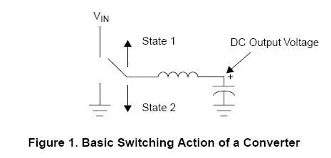
During state 1, the inductor is connected to the input voltage via a (high-side "high-side") MOSFET. During the state 2 process, the inductor is connected to GND. Because of the use of such controllers, inductive grounding can be achieved in two ways: by diode grounding or by (low-side "low-side") MOSFET grounding. If the latter is the case, the converter is called synchronus.
Now consider how the current flowing through the inductor varies in both states. During the state 1 process, one end of the inductor is connected to the input voltage and the other end to the output voltage. For a step-down converter, the input voltage must be higher than the output voltage, thus creating a positive voltage drop across the inductor. In contrast, in the state 2 process, the inductor end that was originally connected to the input voltage is connected to ground. For a buck converter, the output voltage must be positive, thus creating a negative voltage drop across the inductor.
We use the formula to calculate the voltage on the inductance:
V=L(dI/dt)
Thus, when the voltage across the inductor is positive (state 1), the current across the inductor increases; When the voltage across the inductor is negative (state 2), the current across the inductor decreases. The current through the inductor is shown in Figure 2:
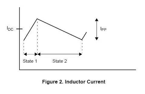
As can be seen from the figure above, the maximum current flowing through the inductor is half the DC current plus the switch peak current. The figure above is also known as ripple current. According to the above formula, we can calculate the peak current:
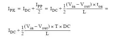
Where, ton is the time of state 1, T is the switching period (the reciprocal of switching frequency), and DC is the duty cycle of state 1.
Warning: The above calculation assumes that the voltage drop across each component (the on-voltage drop on a MOSFET, the on-voltage drop on an inductor, or the forward voltage drop on a Schottky diode in an asynchronous circuit) is negligible compared to the input and output voltages.
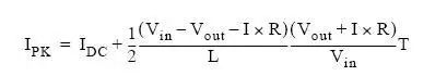
If, the drop of the device is not negligible, the exact calculation shall be made by using the following formula:
Synchronous conversion circuit:
Asynchronous conversion circuit:
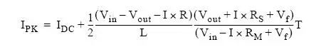
Where, RS is the resistance of inductive resistance plus inductive winding resistance. Vf is the forward voltage drop of a Schottky diode. R is RS plus the MOSFET on-resistance, R= RS +Rm.
The saturation of the inductor core
By calculating the peak current of the inductor, we can find out what is being produced on the inductor. It is easy to see that as the current through the inductor increases, its inductance decreases. This is determined by the physical properties of the core material. How much inductance is reduced is important: if the inductance is reduced too much, the converter will not work properly. When the current through the inductor is large enough to be effective, the current is called "saturation current". This is also the basic parameter of inductance.
In fact, there will always be a "soft" saturation for the switching power inductor in the switching circuit. To understand this concept, look at the actual measured inductance vs. DC current curve:
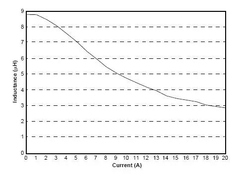
When the current is increased to a certain level, the inductance does not drop sharply, which is called the "soft" saturation property. If the current is increased further, the inductor will be damaged.
Note: inductance drop can occur in many types of inductors. For example, Toroids, Gapped E-cores, etc. However, the rod core inductor does not have this change.
With this soft saturation property, we can see why all converters have a minimum inductance at the DC output current; And because the ripple current changes will not seriously affect the inductance. In all applications it is desirable to keep the ripple current as small as possible because it affects the ripple of the output voltage. This is why most people care about the inductance at the DC output current and ignore the inductance at the ripple current in the Spec.
In the design of switching power supply, the design of inductance brings many challenges for engineers. The engineer should not only select the inductance value, but also consider the current the inductor can withstand, the winding resistance, the mechanical dimensions, and so on. This article focuses on the explanation: DC current effects on inductors. This will also provide the necessary information for selecting the appropriate inductor.
Understand the function of inductors
Inductance is often understood as the L in the LC filter circuit at the output of a switching supply (where C is the output capacitor). While this is true, understanding inductor design requires a deeper understanding of inductor behavior.
In a step-down conversion (typical of Fairchild switching controllers), one end of the inductor is connected to the DC output voltage. The other end is connected to the input voltage or GND by switching frequency.
During state 1, the inductor is connected to the input voltage via a (high-side "high-side") MOSFET. During the state 2 process, the inductor is connected to GND. Because of the use of such controllers, inductive grounding can be achieved in two ways: by diode grounding or by (low-side "low-side") MOSFET grounding. If the latter is the case, the converter is called synchronus.
Now consider how the current flowing through the inductor varies in both states. During the state 1 process, one end of the inductor is connected to the input voltage and the other end to the output voltage. For a step-down converter, the input voltage must be higher than the output voltage, thus creating a positive voltage drop across the inductor. In contrast, in the state 2 process, the inductor end that was originally connected to the input voltage is connected to ground. For a buck converter, the output voltage must be positive, thus creating a negative voltage drop across the inductor.
We use the formula to calculate the voltage on the inductance:
V=L(dI/dt)
Thus, when the voltage across the inductor is positive (state 1), the current across the inductor increases; When the voltage across the inductor is negative (state 2), the current across the inductor decreases. The current through the inductor is shown in Figure 2:
As can be seen from the figure above, the maximum current flowing through the inductor is half the DC current plus the switch peak current. The figure above is also known as ripple current. According to the above formula, we can calculate the peak current:
Where, ton is the time of state 1, T is the switching period (the reciprocal of switching frequency), and DC is the duty cycle of state 1.
Warning: The above calculation assumes that the voltage drop across each component (the on-voltage drop on a MOSFET, the on-voltage drop on an inductor, or the forward voltage drop on a Schottky diode in an asynchronous circuit) is negligible compared to the input and output voltages.
If, the drop of the device is not negligible, the exact calculation shall be made by using the following formula:
Synchronous conversion circuit:
Asynchronous conversion circuit:
Where, RS is the resistance of inductive resistance plus inductive winding resistance. Vf is the forward voltage drop of a Schottky diode. R is RS plus the MOSFET on-resistance, R= RS +Rm.
The saturation of the inductor core
By calculating the peak current of the inductor, we can find out what is being produced on the inductor. It is easy to see that as the current through the inductor increases, its inductance decreases. This is determined by the physical properties of the core material. How much inductance is reduced is important: if the inductance is reduced too much, the converter will not work properly. When the current through the inductor is large enough to be effective, the current is called "saturation current". This is also the basic parameter of inductance.
In fact, there will always be a "soft" saturation for the switching power inductor in the switching circuit. To understand this concept, look at the actual measured inductance vs. DC current curve:
When the current is increased to a certain level, the inductance does not drop sharply, which is called the "soft" saturation property. If the current is increased further, the inductor will be damaged.
Note: inductance drop can occur in many types of inductors. For example, Toroids, Gapped E-cores, etc. However, the rod core inductor does not have this change.
With this soft saturation property, we can see why all converters have a minimum inductance at the DC output current; And because the ripple current changes will not seriously affect the inductance. In all applications it is desirable to keep the ripple current as small as possible because it affects the ripple of the output voltage. This is why most people care about the inductance at the DC output current and ignore the inductance at the ripple current in the Spec.
Share


- About
- Company Profile
- Company Honor
- Products
- FIELD EFFECT TRANSISTOR
- SCHOTTKY DIODES
- ULTRAFAST RECOVERY POWER RECTIFIER
- SIC SCHOTTKY DIODES
- Silicon carbide MOSFET
- Follow
-
Address:Room 402-404,Qianhai ChengJin Building,Moon Bay Boulevard, Nanshan District,Shenzhen
Tel:0755-88327180
Fax:0755-88327190
Email:sunny@hisemicon.com
- Contact
-
.jpg)
WeChat